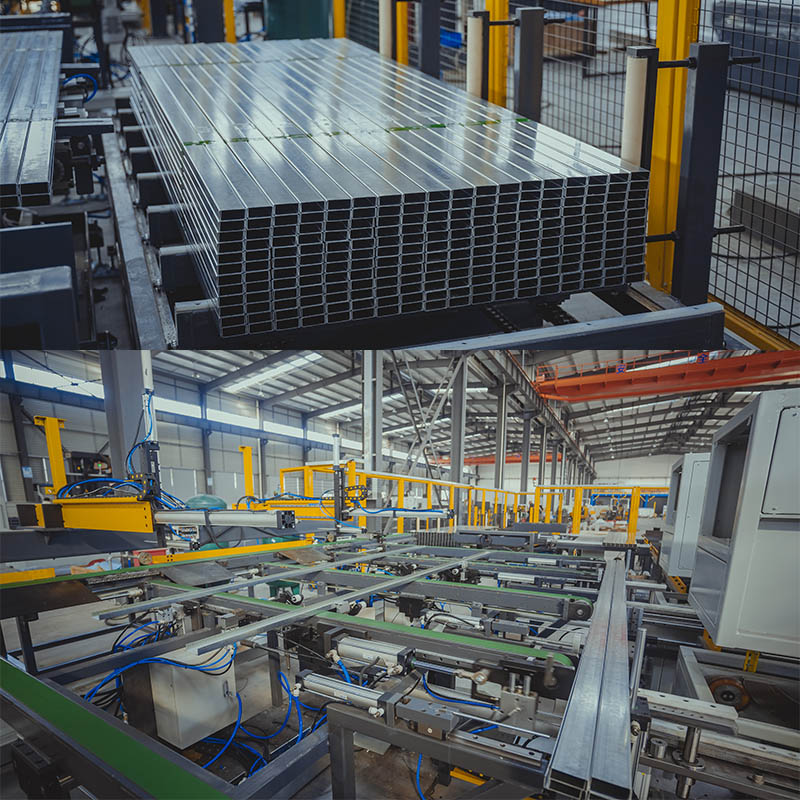
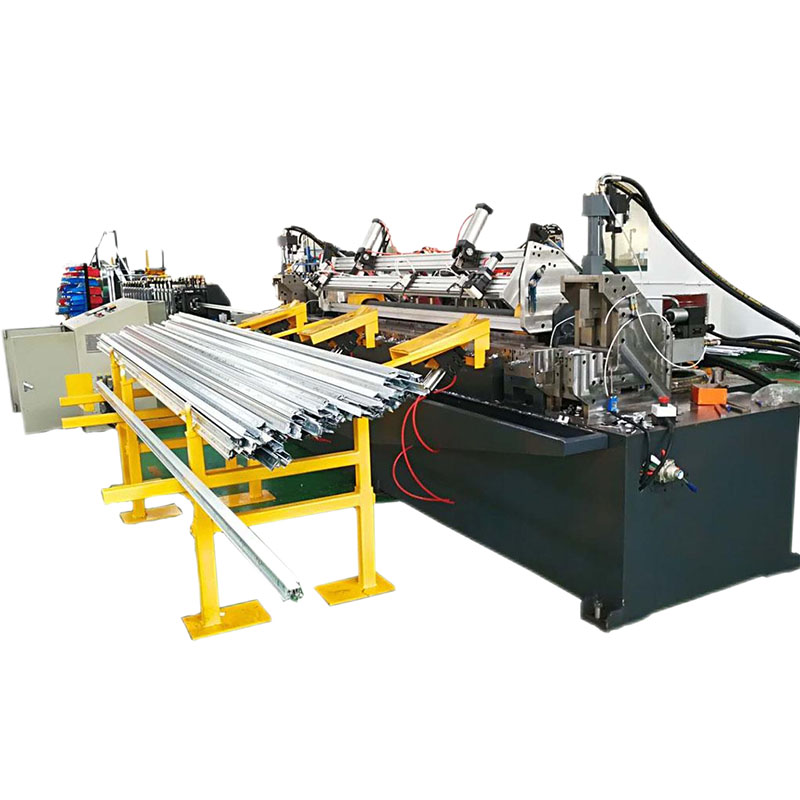
slitting machine for 0.4-1.3mm width 1300mm
| (一) Steel coil raw material parameters | |
| (1) Applicable material | galvanized coil |
| (2) slitting thickness | 0.4mm~1.3 mm |
| (3) Plate width | 300mm~1250mm |
| (4) Inner diameter of steel coil | Φ508mm |
| (5) Outer diameter of steel coil | Φ1600mm |
| (6) Weight of coil | 15 tons |
| (二) Finished product parameters | |
| (1) Width tolerance | ± 0.05mm |
| (2) Bururr length | 0.03 mm |
| (3) Number of split strips | 1mm plate thick, 25 strips |
| (4) Vertical shear straightness | 1mm / 2000mm |
| (5) Full circle diameter of the coil | Φ508mm |
| (6) Outer diameter of decoiler | Φ1600mm |
| (三) Other parameters of the equipment | |
| (1) Unit speed | 0~120m / min |
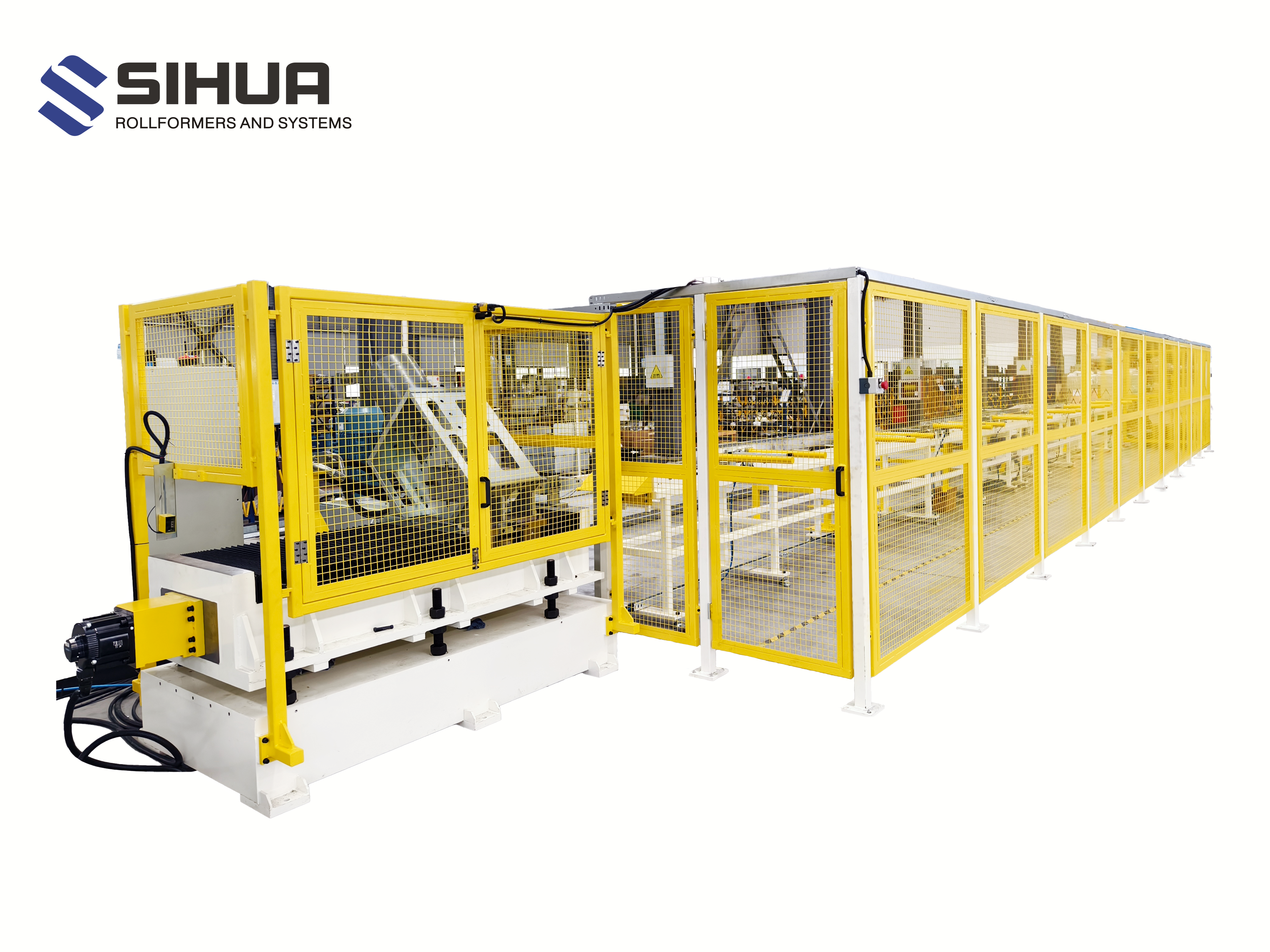
| (2) Floor area (about) | within 17 m |
| (3) Power supply | 380V / 50 HZ three-phase and five-wire |
| (4) Installed capacity | about 160 KW |
| (5) Drive motor | open-coil machine AC11 KW machine ordinary motor AC75 KW machine ordinary motor AC90 KW Hydraulic station motor AC7.5KW |
| (6) Unit direction | facing the operation console from (left) to (right) (forward direction machine) |
| (7) Production operator | 1 technical worker and 2 general workers |
| (8) Device Color | blue |
1.Coil car
2.Hydraulic Decoiler
3.Hydraulic auxiliary support I
4.Live crossing bridge I
5.Side guide and slitting machine
6.scrap winder (both sides)
7.Live crossing bridge II
8.separator and tension table
9.Hydraulic recoiler
10.Hydraulic auxiliary support II
11.Exit coil car for recoiler 1
2.Hydraulic system
13.Electrical control system

1 Coil car (1 set)
(1) Main structure: steel plate, walking wheel, four guide columns, transmission shaft, etc.
(2) Weight-bearing 15 tons, hydraulic motor drive, walking 6 meters per minute.
(3) Oil pressure power: lifting height of 600mm, oil pressure cylinder: FA- Φ125mm (1 branch).
technical parameter
| form | Heavy steel frame, oil pressure and motor control |
| quantity | A |
| Type V surface | Nylon plate + steel plate welding |
| bearing | 15 T |
| Lift trip | 600mm |
| Car walking power | motor |
| Car walking speed | 6m/min |
Structure and use: used to feed the open coder, transport the steel coils from the storage table to the reel of the open coder, trolley walking is controlled by oil pressure motor, and lifting for hydraulic cylinder control.
Lift mechanism: hydraulic cylinder and sliding four-guide column structure, the lifting power is provided by the cylinder, the cylinder pushes the V-type bearing table to realize the function of upper and lower steel coil.
Walking mechanism: oil pressure motor and parallel guide rail structure, the walking power is provided by the oil pressure motor, enabling the car to move horizontally along the axial axis of the open coder. Both ends of the rail limited block, to prevent the car derailment.
2.Hydraulic decoiler (1 set)
technical parameter
| form | Steel plate welded frame, hydraulic expansion mandrel | |
| quantity | A | |
| bearing | 15 T | |
| Steel coil inner diameter | Φ508mm; | |
| Steel coil outer diameter | MAX:Φ1800mm | |
| Open reel arc plate structure | ||
| Arc plate rise and shrinkage range | Φ460mm-Φ520mm | |
| Arc plate | 45 # cast steel (chrome finish) | |
| Open roll brake | 2 sets of disc brakes | |
| Discharge method | Take the initiative to feed | |
| Open roll power | 11KW motor | |
Open roll and close roll removal device with roll pressure
A、 function:
Bearing the steel coil, tighten the inner diameter of the coil, open the coil or recover the coil.
Support the coil plate and provide tension to the steel strip, consisting of the frame, main shaft, expansion rolling drum, uncoil crushing device, auxiliary support, brake device and power part.
B、 structure
a) Main frame: made of type steel, A3 steel plate, # 45 steel, two bearing bearings are bored at one time to ensure the concentricity of spindle installation and no radial beating.
b) Main shaft: composed of 40 Cr round steel drill diameter of 85mm through hole, quality adjustment and then refined car, roller shaft diameter of 190mm, bearing weight of 15 tons.
c) Raise and shrink drum: adopt slide type push and pull expansion drum; four arc plate (no. 45 steel), line cut slider pair, expansion diameter: Ф470mm-520mm; the effective working length of the drum is 1300mm, the integral mandrel ensures the concentricity of the drum increases and decreases, the drum rises to the diameter of 508mm on the lathe car round, the surface electroplating hard chromium.
d) Unroll press device: composed of press roller, support arm and oil cylinder; press roller bread polyurethane grease and the material head will not be loosened and the support arm is lifted by the hydraulic cylinder.
e) Brake device: using pneumatic disc brake assembly, brake strength can be adjusted, parking when the brake is tight, to ensure that the standby and boot state will not be loose rolling, so as not to scrape the plate surface when loose rolling. Synchronization control with open roll feed.
f) Oil pressure power: push and pull the mandrel: oil pressure cylinder model specification: Ф 150150mm, using rotary joint oil supply mode (Taiwan oilfield); press lifting hydraulic cylinder Ф 80220 mm.
g) Electrical power: open winding machine power adopts 11KW AC motor with closed gearbox drive (1 set)
3.Hydraulic auxiliary support (1unit)
(1) Application: Support the cantilever end of the roll to increase the rigidity of the roll.
(2) The auxiliary support is an elbow rod mechanism, which is lifted or dropped by the swing arm of the hydraulic cylinder.
(3) When opening the roll, the swing arm is raised to hold the cantilever end of the winding machine, and when rolling the roll, the swing arm falls.
4.Live crossing bridge (1 unit)
(1) Main structure: the frame is welded with steel plate.
(2) Oil pressure power: upper and lower: oil pressure cylinder: CA- Φ 80mm (1).
technical parameter:
| form | The frame and the transition bracket are steel plate welding parts, and the transition roll is an adhesive roll |
| quantity | A |
| Live sleeve (length depth) | 3000mm×3500mm |
| The way to lift a set of tables | Hydraulic cylinder supports the lift |
Structure and use: used to control the synchronization and buffer of steel strip speed between stripper and feeder. The table is made of nylon board to ensure that the plate surface is not scratched. The position of three pairs of electric eye control steel belts in the living sleeve pit can maintain enough storage in the pit.
5. Side guide and slitting machine (1set )
Technical parameters of the lateral guide positioning
| form | Steel plate welding base, stand of roll and frame |
| quantity | A |
| Cross board width | 200-1250mm |
| Width adjustment | Adjust from the hand wheel |
| The roll material | GCr15 steel |
| niproll | Φ120mm×1300mm |
Structure and use: for plate width orientation to prevent the steel plate from deviation. Vertical rollers are provided on both sides of the plate width direction, fixed on their respective sliding seats, and the slide seat is adjusted on the guide rail along the plate width direction to accommodate different plate width. The vertical roller is quenched, and the roller surface is chroplated to increase the surface hardness and prevent mechanical wear.
Technical parameters of machine
| form | Steel plate welding base, power gear box, archway and frame |
| quantity | A set |
| Divide the speed | 120m/min |
| Shaft diameter | Φ180mm×1300mm |
| material quality | 42CrMo |
| Span size (quoted excluding this) | Φ300mm Φ180mm 10mm (OD ID thickness) |
| Power of main motor | AC75Kw Motor |
| Mobile archway motor | Mounted outside the rack without affecting the knife |
Structure and use: the machine is a device that longitudinal shear with vertically into various widths. The width of the finished product can be flexibly changed by replacing the composite sleeve. The knife shaft is adjusted by the lower shaft and the upper shaft for the synchronous knife shaft spacing, which can accurately control the gap between the upper shaft and the lower shaft. The upper and lower shafts are fastened with nuts as axial direction, and the shaft end of the upper and lower blades. Use side boot frame (motor drive) to replace the blade.
(1) Main structure: steel plate, casting seat, synchronous gear box, universal drive, electric screw lifting device.
(2) Tool shaft material: 40 Cr, diameter of knife shaft: Φ180mm 1300mm, medium frequency treatment after rough processing, grinding, hard chromium plating, 20mm with key groove.
(3) The knife shaft lock: the nut locks the tool.
(4) Press plate adjustment of a group of bracket, up and down lifting adjustment, fixed wood with.
(5) Tool seat movement: electric in and out, knife shaft lifting, electric synchronization.
(6) Shear power: 75 KW ordinary motor with frequency converter.
6. Scrap winder (both sides)
one connection; independent frequency conversion tension control
technical parameter:
| form | Rack for welded steel plates |
| structure | Left and right independent feeding connected structure; reel, press shaft and transmission composition. Controlled by the oil cylinder for easy unloading |
| quantity | Two; one left and right |
| Receive the width of the scrap edge | And 2-10mm / one side |
| coiling speed | 0-120m/min |
| Roll the weight | MAX:300Kg |
| Power of main motor | AC 3 Kw (two) |
| breathing | Mechanical expansion |
Structure and use: the side material winding machine is the device of the two sides of the strip winding. Motor drive, with another discharge oil cylinder, stable and durable.
7. Live crossing bridge II (1 unit)
(1) Main structure: the frame is welded with steel plate.
(2) Oil pressure power: upper and lower: oil pressure cylinder: CA- Φ 80mm (1).
technical parameter:
| form | The frame and the transition bracket are all steel plate welding parts, and the transition roll is a rubber roll |
| quantity | A |
| Live sleeve (length depth) | 3000mm×5000mm |
| The way to lift a set of tables | Hydraulic cylinder supports the lift |
| Tailor press plate | Prevent the plate from falling into the pit and damage the material |
Structure and use: used to control the synchronization and buffer of steel strip speed between retractor and stripper. The table is made of nylon board to ensure that the plate surface is not scratched.
8. Separator and tension table
(1) Main structure: steel plate, separation roller, PU rubber, etc.
(2) Tension pad: top spread with wool felt.
(3) Rebelt roller: PU rubber, Φ350mm.
(4) Oil pressure power: tension pad lifting: oil pressure cylinder: FA- Φ 80mm (2 pieces).
technical parameter:
| form | Base and frame for steel plate welding |
| quantity | A set |
| Sector size | Φ80×Φ180*3 |
| Separate set size | Φ80×Φ110×& |
| The middle pressure roller | Vertical lift |
Structure and use: the longitudinal shear strip separation, to prevent the tensioning machine when stacking, easy to collect. There are two sets of separation discs. The separation disc shaft can be removed from the operating side to facilitate replacement and cleaning.
| form | Steel plate welding base, frame, brake system composition |
| quantity | A |
| Pressure plate type | The plate is driven by the cylinder to achieve the ideal compression tension |
Function: Position the steel strip and apply uniform tension to each steel strip for re rolling, and the tension generated determines the tightness of the rewinding. The uniform tension can make the winding neat; it is mainly composed of main frame, front separation frame, pressing machine, rear separation frame, tension stage and guide roller.
B, structure:
● Main frame structure: made of profile, steel plate assembly welding, machining base surface after annealing.
● Front separation frame: adopt guide type independent frame, the frame is connected through the two surfaces and the separator is mounted on the partition shaft for the body and sleeve, which is very convenient; the front separation frame can move up and down relative to the main frame and can stop at any height.
● Tension platform: it is composed of side plate archway, upper gantry frame, lower pad plate, upper pad plate and oil cylinder. The wool felt can be fixed on the upper and lower pad plate. The plate belt passes between the upper and lower pad plates, and the pressing pad plate produces tension. The upper pad plate is driven by two oil cylinders synchronously.
● Guide roller, plate device
Guide roller: by bearing seat, seamless steel pipe wrapped PU rubber, dynamic balance treatment, the function is to guide the plate belt into the winder.
Plate device: composed of rack and drive system. The plate device adopts hydraulic drive structure, its function is to send the plate head to the winder.
9 Hydraulic recoiler
(1) Main structure: drum adopts seamless structure; steel plate, separation roller, main shaft, four arc plate (zigzag), sliding block, side plate, bearing, bearing seat, push and pull cylinder, box reducer, hydraulic push device, steam brake, etc.
(2) Reel expansion and contraction: Φ480mm~ Φ508mm, with jaw device, oil pressure cylinder: FA- Φ150mm (1 branch).
(3) Electrical power: 90 KW ordinary motor is equipped with frequency converter.
Technical parameters of the winder
| form | Steel plate welded frame, single arm hydraulic expansion mandrel and gear box structure |
| quantity | A |
| bearing | 15 T |
| Steel coil inner diameter | Φ508mm |
| Spindle material | 42 Cr Mo |
| Reel flap arc plate | 45 # steel after quality conditioning treatment, the surface is coated with hard chromium |
| Condensed clamp mouth | Oil cylinder drive up and down |
| Steel coil outer diameter | MAX:Φ1800mm |
| Push material board | Oil cylinder push |
| brake assembly | Disc brake type brake |
| Power of main motor | AC90 Kw Motor |
Structure and use: This equipment is used to rewinding the strip after longitudinal shear. It is composed of frame body, drum, transmission system, rise and shrinkage system, braking system, lubrication system, hydraulic system, etc.
Transmission system: the spindle is driven by the motor. Increase and shrinkage system: the tension is provided by the rise and shrinkage oil cylinder to make the sliding seat on the main shaft produce displacement sliding, and the qi shape slider and the sliding seat produce displacement to realize the rise and contraction of the drum.
Technical parameters of the separator shaft pressure arm
| form | Base and frame for steel plate welding |
| quantity | A |
| Sector size | Φ80×Φ180×3 |
| Separate set size | Φ80×Φ110×& |
Structure and use: This equipment is used to rewinding the longitudinal cutting. The press material arm is swung by the oil cylinder. The pressing shaft can be manually spread around the fixed fulcrum for the replacement of the isolation plate (pad).
10 Hydraulic auxiliary support II
(1) Application: Support the cantilever end of the roll to increase the rigidity of the roll.
(2) The auxiliary support is an elbow rod mechanism, which is lifted or dropped by the swing arm of the hydraulic cylinder.
(3) When receiving the roll, the swing arm is raised to hold the cantilever end of the winding machine, and when the roll, the swing arm falls.
11 Exit coil car for recoiler(1)
(1) Main structure: steel plate, walking wheel, four guide columns, transmission shaft, etc.
(2) Hydraulic motor drive, walk 6 meters per minute.
(3) Oil pressure power: lifting height of 600mm, oil pressure cylinder: FA- Φ125mm (1 branch).
Technical parameter:
| form | Heavy steel frame, oil pressure and motor control |
| quantity | A |
| Type V surface | Steel plate welding |
| bearing | 15 T |
| Lift trip | 600mm |
| Car walking power | motor |
| Car walking speed | 7m/min |
Structure and use: for unloading the coil, unloading the steel coil from the coil, trolley walking for oil pressure motor control, lifting and lifting for hydraulic cylinder control.
Lift mechanism: hydraulic cylinder and sliding guide column structure, the lifting power is provided by the cylinder, the cylinder pushes the V-type bearing table to realize the function of upper and lower steel coil, and the unloading trolley with anti-inverted rod.
Walking mechanism: the oil pressure motor and the parallel guide rail structure. The walking power is provided by the oil pressure motor to make the car move horizontally along the coil axis of the roller. Both ends of the rail limited block to prevent the car derailment.
12 Hydraulic system (1 set)
(1) Main structure: steel plate welded oil tank, capacity of 300kg and all kinds of oil pressure valves, oil panels.
(2) Power: Class E 7.5KW motor and oil pump, 30ML, normal pressure 70kg / cm2, maximum pressure: 140kg / cm.
technical parameter:
| quantity | A set |
| fuel tankage | 300L |
| Oil pump displacement | 25ml/r |
| System working pressure | 12MPa |
| power of motor | 7.5 KW |
| cooling-down method | Wind cooling |
| working temperature | 0℃—60℃ |
| service substance | N68 anti-wear hydraulic oil |
Composition and use: to control the operation of the hydraulic part of the whole production line. Using centralized control, the system consists of one hydraulic station, multiple valve stacks and several pipelines. Mainly have oil tank body, oil pump electric unit, hydraulic valve pile, hydraulic pipeline, etc.
13 Electric control system
(1) Electronic control operating table.
(2) Power supply voltage: three-phase 380VAC ± 10% Frequency: 50Hz ± 1
(3) Composition and use: The system is equipped with an operation station, the whole line adopts centralized control, the operation station has digital display, high and low speed adjustment, manual feed, continuous segmentation, fault alarm and other functions. Speed regulation system, program controller (PLC) using Taiwan Yong hong company products. Other electrical control components imported products or joint venture products of the same grade. Console, push-button box, detection components and cables and wires. With touch screen control, it can easily set and modify production process parameters, including speed, manual and automatic switching, and monitor the operation status of each parts. Ensure the safe and efficient operation of the production line.
14 Brand and supplier description:
Mechanical part
| order number | name | producer | remarks |
| 1 | bearing | Japan imported the NSK | Divide the host |
| 2 | bearing | Ha axis, tile axis | accessory equipment |
| 3 | Motor gear machine | Ying a | |
| 4 | gear reducer | Guo MAO |
Pneumatic equipment
| order number | name | producer | remarks |
| 1 | air cylinder | Domestic quality products | |
| 2 | electromagnetic valve | stars | |
| 3 | speed control valve | stars |
Hydraulic part
| order number | name | producer | remarks |
| 1 | electromagnetic directional valve | Oil kun | |
| 2 | electromagnetic relief valve | Oil kun | |
| 3 | chiller | Domestic quality products |
Electrical total
|
order number |
name |
supplier |
|
1 |
PLC |
Taiwan yong hong |
|
2 |
human-computer interface |
Weilun, Taiwan |
|
3 |
frequency transformer |
Huichuan |
|
4 |
auxiliary relay |
Schneider |
|
5 |
Ordinary motor |
Jiang Sheng |
|
6 |
Low voltage components |
Schneider |
15 Random attachment:
(1) Installation drawing of mechanical foundation, bolt distribution and production line layout drawing.
(2) Attachment: 20 pieces; 120 collected nylon pions; 20 tension pieces; 120 tension pions; 1 cutter shaft.
|
order number |
Description description |
scope of supply |
remarks |
|
|
Seller |
buyer |
|
||
| 1 |
design |
|||
| 1.1 |
Design schedule |
√ |
|
|
| 1.2 |
machine design |
√ |
|
|
| 1.3 |
Electrical design for machine operation |
√ |
|
|
| 1.4 |
Circuit design for air pressure and hydraulic pressure |
√ |
|
|
| 1.5 |
Layout design of the production line |
√ |
|
|
| 2 |
make |
|||
| 2.1 |
Make the schedule |
√ |
|
|
| 2.2 |
Mechanical and electrical part of the manufacturing |
√ |
|
|
| 2.3 |
Inspection and testing of manufacturing |
√ |
|
|
| 2.4 |
spray paint |
√ |
|
|
| 2.5 |
pack |
√ |
|
|
| 3 |
terms of delivery |
|||
| 3.1 |
On-site unloading |
|
√ |
|
| 3.2 |
Site unloading equipment (crane, etc.) |
|
√ |
|
| 3.3 |
Site equipment confirmation and storage |
|
√ |
|
| 4 |
foundation work |
|||
| 4.1 |
Civil engineering foundation design |
√ |
|
|
| 4.2 |
Foundation engineering and consulting |
√ |
|
seller provides the basic map |
| 4.3 |
Inspection of the basic works |
√ |
√ |
|
| 4.4 |
bay bolt |
√ |
|
|
| 4.5 |
Machine pad (flat pad iron, inclined iron) |
√ |
|
|
| 4.6 |
Grout and mortar are poured into the mechanical foundation |
|
√ |
|
| 4.7 |
The mortar is injected into the foot hole of the equipment |
|
√ |
|
| 4.8 |
Burbedded in concrete (H-, etc.) |
|
√ |
|
| 5 |
erection work |
|||
| 5.1 |
Installation equipment (driving vehicle, truck crane, etc.) |
|
√ |
|
| 5.2 |
replacement tool |
√ |
|
|
| 5.3 |
Installation material (hydraulic pneumatic pipe and wiring) |
√ |
|
|
| 6 |
safety precautions |
|||
| 6.1 |
Ditch cover plate and submersible pump |
|
√ |
|
| 6.2 |
guardrail |
√ |
|
|
| 7 |
Hydraulic air pressure and freezing engineering |
|||
| 7.1 |
hydraulic unit |
|
|
|
| 7.2 |
Hydraulic drain engineering (in the equipment) |
√ |
|
|
| 7.3 |
Hydraulic drain pipe works (in the trench) |
√ |
|
|
| 8 |
electrical engineering |
|||
| 8.1 |
Install the required power |
|
√ |
|
| 8.2 |
Primary cable from the substation to the control panel and the distribution cabinet |
|
√ |
|
| 8.3 |
A cable trench |
|
√ |
|
| 8.4 |
Secondary wiring of the mainline cabinet to the machine |
√ |
|
|
| 8.5 |
Cable slot for the secondary wiring |
√ |
|
|
| 8.6 |
Motor and drive controller |
√ |
|
|
| 8.7 |
Wiring and drain piping in the machine |
√ |
|
|
| 8.8 |
Each line to the power distribution cabinet |
√ |
|
|
| 8.9 |
Approval of the use of lighting and electrical appliances |
|
√ |
|
| 9 |
test run |
|||
| 9.1 |
Materials for test run |
|
√ |
|
| 9.2 |
Test worker |
|
√ |
|
| 9.3 |
Oil injection, gear oil, hydraulic oil, etc |
|
√ |
|
| 9.4 |
Operating maintenance tools |
√ |
|
|
| 10 |
Training and after-sales service |
|||
| 10.1 |
Operation manual and maintenance manual |
√ |
|
|
| 10.2 |
Operation and maintenance training |
√ |
|
|
(1) Security alarm warning system;
1.Configure the joint operation condition confirmation lock (safety lock) and alarm prompt for each post.
2.Each operating station, including feeding, main operation, unloading, etc., can operate the alarm independently.
3.When each moving device is working, the alarm prompts.
(2) Safety interlock device (infrared detection and alarm for critical hazard part)
(3) Equipment clip roller, connecting shaft, rotating chain, exposed brake pads and other operating bodies must be equipped with protective cover and safety railings around the sleeve.
(4) Warning signs for dangerous parts and important parts of the equipment
(5) The rotating body shall be marked with obvious colors, which shall be distinguished from the color of the body equipment (in yellow)
1.The Buyer shall provide the cooling water and the gas source to the equipment interface.
2.The Buyer shall own power supply distribution box (three phase five lines), whose capacity must meet the power requirements of the unit.
3.There are more than three outlet terminals in the power distribution box.
4.The power distribution box is within 5m from the main operation cabinet.
5.The Buyer is responsible for directing the power supply to the operating station.
6.The buyer shall provide one air compressor.
7.The Buyer shall provide gear oil, hydraulic oil, lubricating oil and oil grade provided by the Seller.
8.The Buyer shall provide the necessary materials for commissioning and related auxiliary tools and equipment.